
Introduction
Knowing the resonant frequency of your secondary coil is an important first step in the initial operation of your DIY Tesla coil. This along with knowing the resonant frequency profile of your primary circuit allows you to find a good tuning starting point for your Tesla coil. Also, I need to mention that this method is certainly not the only way to perform this measurement, but it is the method I use with my own Tesla coils and i find it easy and accurate.
Theory of Test
This measurement involves using the output of a waveform generator to drive the base of a secondary coil through a high ohm resistor. The resistor and secondary impedance form a voltage divider at the output of the waveform generator. When the secondary coil is at resonance, its impedance will be at a minimum, therefore, causing the voltage at the output of this voltage divider to be at a minimum as well. The oscilloscope is used to look at this divider voltage and as we sweep through a range of frequencies, we will be looking for the frequency where this voltage minimum occurs.
It is important to note that there are other resonant frequency harmonics which will also cause voltage minimums. These other minimums occur at frequencies higher than the fundamental resonant frequency, therefore it is very important to start your frequency sweep at low frequency and gradually increase the frequency from that initial starting point. For most secondary coils, 50kHz would be a good starting point to begin your sweep.
What is Needed?
The following equipment and components are required to perform this test.
- Secondary coil
- Toroid - Use the exact toroid you will be using along with this secondary coil
- Oscilloscope with 10x probe or similar
- Function or waveform generator preferably with a sine wave output
- 5k to 20k resistor - The value of the resistor is not critical, but should be within this range.
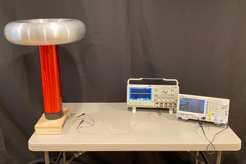
The above photo shows the set-up for measuring the secondary coil resonant frequency. Note that the secondary coil and toroid should be physically away from nearby objects including yourself, as these will cause the resonant frequency to change.
Set-up
- Set the secondary coil in an upright position in a location that is away from nearby objects including yourself. Nearby objects will change the resonant frequency of the secondary coil, so you want to be sure you and your equipment are far enough away to not affect the measurements.
- Connect the base of the secondary through a wire to a 5k-20k resistor which is installed at the output of your waveform generator. The resistor should be installed directly at the output terminal of the waveform generator.
- Connect an oscilloscope probe as shown in the photo above. Connect the probe on the secondary coil side of the resistor and the oscilloscope ground clip directly to the ground (return) of the waveform generator. The oscilloscope probe must be on the side of the resistor closest to the secondary coil or this measurement will not work.
Measurement Procedure
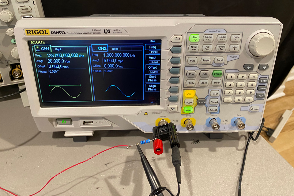
- Set the output of your waveform generator to sine wave.
- Set the output level of your waveform generator to its maximum level. Do not exceed 30V as this would pose a safety hazard.
- Set the starting frequency to 50kHz.
- Gradually increase the frequency of the waveform generator until a voltage minimum is viewed on the oscilloscope. The frequency at which this voltage minimum occurs is the fundamental resonant frequency of your secondary coil.
- Place the toroid on your secondary coil.
- Set the starting frequency to 50kHz.
- Again, gradually increase the frequency of the waveform generator until a voltage minimum is viewed on the oscilloscope. The frequency at which this voltage minimum occurs is the fundamental resonant frequency of your secondary / toroid assembly. This frequency will always be lower than the unloaded secondary coil by itself due to the added capacitance the toroid adds to the secondary coil.
Conclusion
After performing these two measurements, you will have two important values:
- Unloaded secondary coil resonant frequency
- Secondary / toroid assembly resonant frequency
The secondary / toroid resonant frequency will be the number you use along with your primary circuit resonant frequency characterization to determine the initial starting location of where to tap your primary coil for a proper tune. This will be covered in a separate blog posting.
You can also use the two values above to back calculate the capacitance loading of your toroid. This will also be covered in a separate blog posting.
Thank you for watching and reading this blog.